Today analog oscilloscopes have been completely replaced by digital ones, however the fascination of such vintage stuff cannot be explained to those who have never used one. This is not a debate about which one is better: nowadays all kind of measurements are performed using DSO and is very difficult to find out an old glorious analog scope. If you have it and if it isn’t working, before throwing it away think that you have in your hands an old electronic device made by BJT, JFET, diodes, discrete components and a few logic gates, flip flop and multivibrators, that kind of stuff that you can fix by yourself.
We have an old analog 40 MHz oscilloscope wich suddenly stopped work and the only trace we had on it was a vertical line, independently by which kind of signal we had on the input and and such line was completely right shifted on the screen:
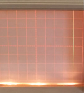
Something in the horizontal section isn’t working but which part, which components? Fortunatly in the ’90 it was not so strange to have an instrument with a user manual, which was including the detailed schematic as well. How to fix the faulty components without another oscilloscope? Pretty difficult but don’t forget that some basic controls can be performed using a common digital multimeter. First check that power supply voltages are the ones required by the instrument as shown in the schematic. Ok, there is no faulty related to the power supply section, all voltages in the horizontal section look good. Let’s have a look at the horizontal amplifier: everything looks ok. What about the sweep generator? After some test performed using only the DMM, we’ve found a little PNP BJT with the BC junction faulty. This PNP is related to the sweep generator logic:


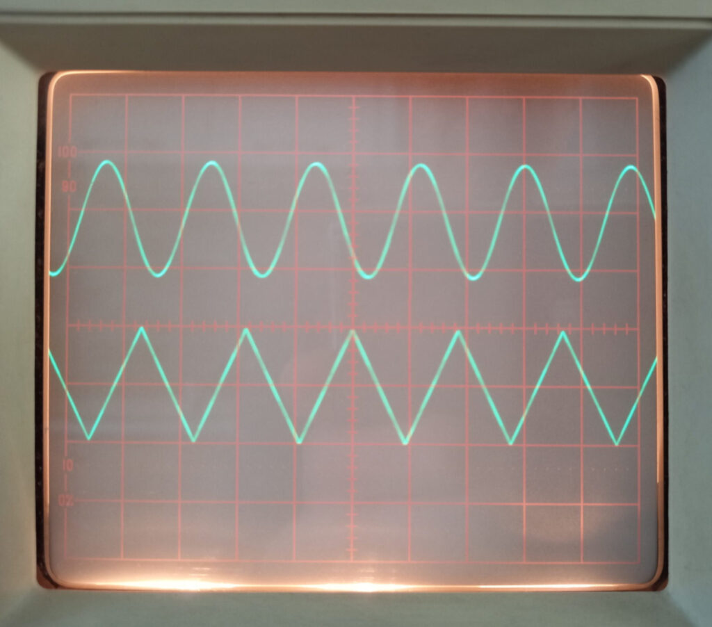
Could be so easy? Let’s try: after replacing Q310, a 2N3906 with a BC557 already available to us, things started working as required again! Bingo! Only a tiny TO92 BJT was causing such fault!
Well done.. Ive a goldstar 9020p similar fault.. On start up the trace is normal with 50 hertz sine. after a few secs goes into a vertical line on right.. Change the timbase to usecs and the waveform is there.. Only steady on 2us…the – 12v in sweep section is 11.3..indicating a partial drain.. I ve been busy fault finding for weeks on n off.. It’s really nightmare as it’s double sided board.. With surface mount components not easy to remove…. .. They soldered both ends.. Any help will be much appreciated..