 This is an example of a simple and cheap milliohmmeter that can be made by every maker. The core of the circuit are a current source (LT3092) and a current sense (INA225): a costant current flows through the milliohm resistor under test and the voltage at the current sense output gives the value of the resistor (V=R*I).
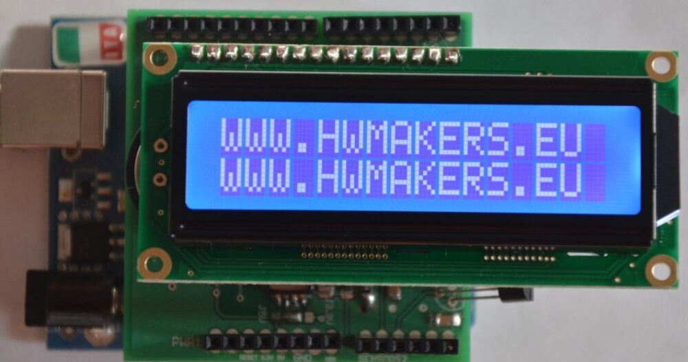
The milliohmmeter can be used as a stand alone instrument by adding a MCU with at least 10 bit ADC and a LCD display or it can be used togheter with a DMM.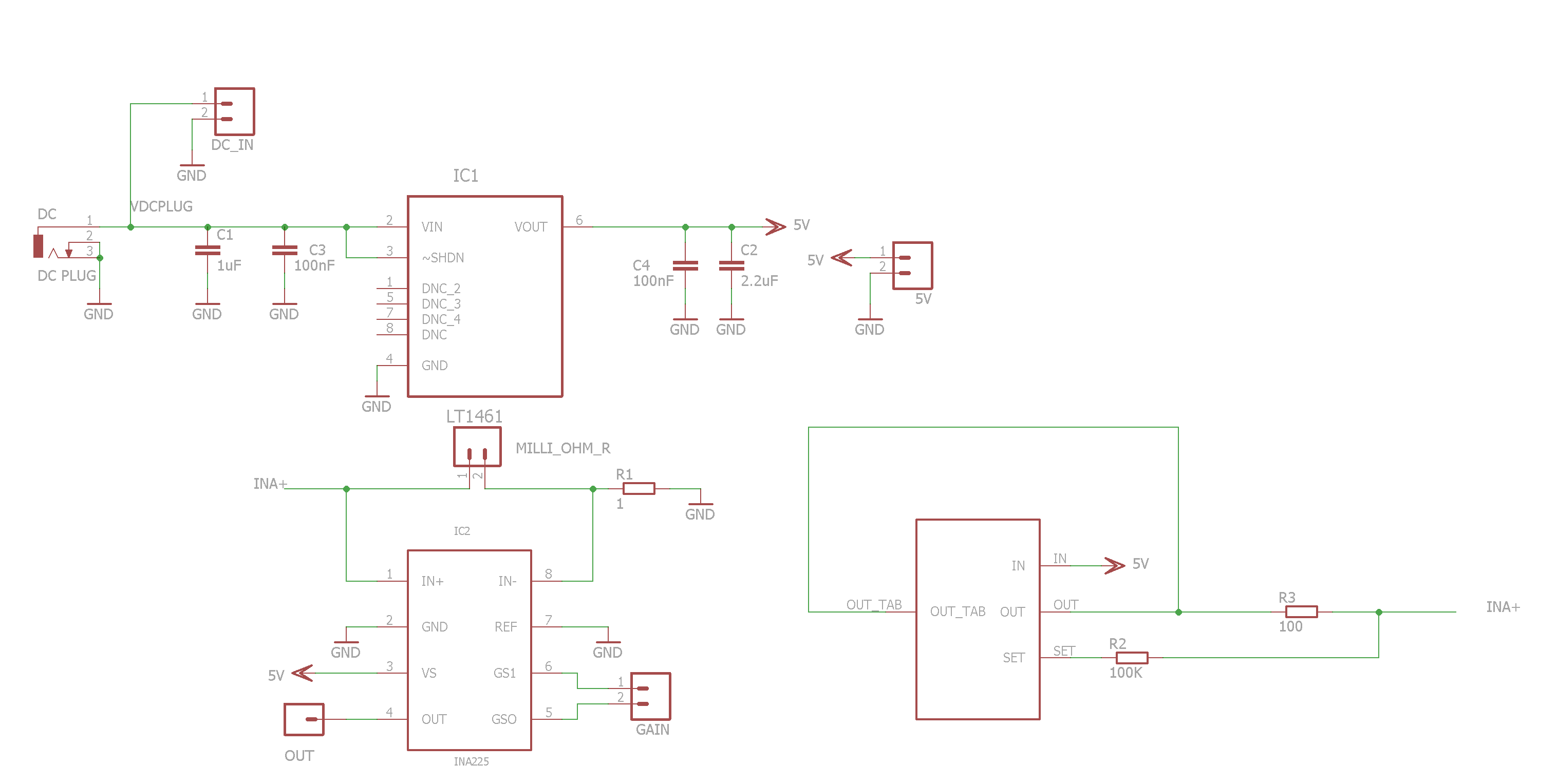
Current out from LT3092 can be set between 0.5 mA and 200 mA with 1% accuracy; INA225 gain can be set to 25, 50, 100 or 200 (0.3% accuracy). By setting Iout from current source equal to 10mA (Iout=10*R2/R3 uA) and current sense gain equal to 100, 1Ω = 1V and 1mΩ = 1mV as such the milliohm resistor value can be easily measured in mV using a DMM, without any kind of conversion. A voltage reference (LT1461) has been added to the circuit in order to have a precise and stable voltage, useful to power both the current source and the current sense as well as the the MCU and its ADC in case we want to have a stand alone milliohmmeter.
Following a simple example of code running on mbed freescale KL-25Z:
#include “mbed.h”
Serial pc(USBTX, USBRX); // tx, rx
float VADC=2.922; //ADC VOLTAGE REFERENCE (EQUAL TO V SUPPLY)
//float IO=10.0; //COSTANT CURRENT
//float GAIN=100.0; //INA225 GAIN
//BOTH NOT REQUIRED IF SET LIKE THIS (1 Ω = 1 V)
float RO=0.021; //RESISTANCE OF CONNECTING CABLES (COMPENSATION)
float STAMPA_R = 0;
AnalogIn resistor(A0); //CONNECTED TO INA225 OUT
float ohm()
{
float R=0.0;
float RADC=resistor.read();
R = VADC*RADC-RO; //IF IO=10mA AND INA225 GAIN 100 -> (1 Ω = 1 V)
wait_ms(100);
return R;
}
int main()
{
while (1) {
STAMPA_R= (ohm());
pc.printf(“R = “);
pc.printf(“%1.3f”,STAMPA_R); //R IN OHM WITH 3 DECIMALS (1mΩ OF RESOLUTION)
pc.printf(“Ω”);
pc.printf(“\r”);
wait_ms(500);
}
}
mbed serial output of a 0.22Ω 5W resistor:

Cool. You should make this commercially available, at least the PCB. Failing that, can you provide the pcb file? I can make my own pcbs.
Thank you for your appreciation. The board is just a concept, as such, there are no PCB available for the moment; anyway if someone thinks gerber files could be useful, they could be added to the project.
Hi Bob. Nice little writeup!
My question is however, your photo of the board uses the LT1451 (461AI5) Voltage reference. Thats a 5V reference Voltage IC. Your code however refers to a 2.922 Voltage reference. Did I miss something? or is that intentional?
Hi,
voltage reference IC is a 5V LT1461 (top silk wrongly reports LT1416); VADC refer to ADC reference voltage which is not the same on the milliohmmeter board because we’ve tested the instrument using a mbed KL-25Z which is supplied by 2.922V (measured to improve reading accuracy).
“wow it”s really useful.”
Thank you Bob for your appreciation.
Hardware Makers